The crate provides three types for working with memory mapped registers: ReadWrite, ReadOnly, and WriteOnly, providing read-write, read-only, and write-only functionality, respectively. These types implement the Readable, Writeable and ReadWriteable traits.
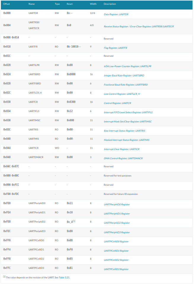
Defining the registers is done with the register_structs macro, which expects for each register an offset, a field name, and a type. Registers must be declared in increasing order of offsets and contiguously. Gaps when defining the registers must be explicitly annotated with an offset and gap identifier (by convention using a field named _reservedN), but without a type. The macro will then automatically take care of calculating the gap size and inserting a suitable filler struct. The end of the struct is marked with its size and the @END keyword, effectively pointing to the offset immediately past the list of registers.
use tock_registers::{registers::{ReadOnly, ReadWrite, WriteOnly}, register_bitfields, register_structs};
pubconst PL011REGS: *mut PL011Regs = (0x0900_0000) as *mut PL011Regs;
register_bitfields![ u32,
pub UARTDR [ DATA OFFSET(0) NUMBITS(8) [] ], /// Flag Register pub UARTFR [ /// Transmit FIFO full. The meaning of this bit depends on the /// state of the FEN bit in the UARTLCR_ LCRH Register. If the /// FIFO is disabled, this bit is set when the transmit /// holding register is full. If the FIFO is enabled, the TXFF /// bit is set when the transmit FIFO is full. TXFF OFFSET(6) NUMBITS(1) [],
/// Receive FIFO empty. The meaning of this bit depends on the /// state of the FEN bit in the UARTLCR_H Register. If the /// FIFO is disabled, this bit is set when the receive holding /// register is empty. If the FIFO is enabled, the RXFE bit is /// set when the receive FIFO is empty. RXFE OFFSET(4) NUMBITS(1) [] ],
/// Line Control register pub UARTLCR_H [ /// Parity enable. If this bit is set to 1, parity checking and generation /// is enabled, else parity is disabled and no parity bit added to the data frame. PEN OFFSET(1) NUMBITS(1) [ Disabled = 0, Enabled = 1 ], /// Two stop bits select. If this bit is set to 1, two stop bits are transmitted /// at the end of the frame. STP2 OFFSET(3) NUMBITS(1) [ Stop1 = 0, Stop2 = 1 ], /// Enable FIFOs. FEN OFFSET(4) NUMBITS(1) [ Disabled = 0, Enabled = 1 ],
/// Word length. These bits indicate the number of data bits /// transmitted or received in a frame. WLEN OFFSET(5) NUMBITS(2) [ FiveBit = 0b00, SixBit = 0b01, SevenBit = 0b10, EightBit = 0b11 ] ],
/// Control Register pub UARTCR [ /// Receive enable. If this bit is set to 1, the receive /// section of the UART is enabled. Data reception occurs for /// UART signals. When the UART is disabled in the middle of /// reception, it completes the current character before /// stopping. RXE OFFSET(9) NUMBITS(1) [ Disabled = 0, Enabled = 1 ],
/// Transmit enable. If this bit is set to 1, the transmit /// section of the UART is enabled. Data transmission occurs /// for UART signals. When the UART is disabled in the middle /// of transmission, it completes the current character before /// stopping. TXE OFFSET(8) NUMBITS(1) [ Disabled = 0, Enabled = 1 ],
/// UART enable UARTEN OFFSET(0) NUMBITS(1) [ /// If the UART is disabled in the middle of transmission /// or reception, it completes the current character /// before stopping. Disabled = 0, Enabled = 1 ] ],
pub UARTIMSC [ RXIM OFFSET(4) NUMBITS(1) [ Disabled = 0, Enabled = 1 ] ], /// Interupt Clear Register pub UARTICR [ /// Meta field for all pending interrupts ALL OFFSET(0) NUMBITS(11) [ Clear = 0x7ff ] ] ];